
Plastic Cap Moulds · 11 min read
Published: October 4, 2026
Plastic Cap Mould Ejection and Demoulding: A Buyer Validation Guide
Treat cap release as a measurable production requirement, not a cosmetic afterthought.
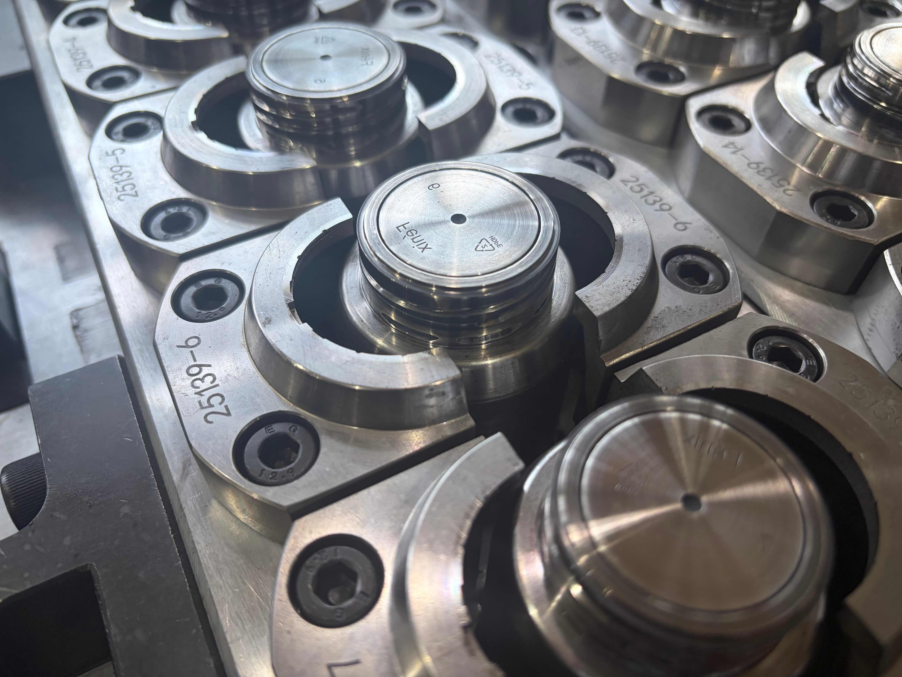
Cap buyers often compare cavity count, cycle time and hot-runner options before discussing how each closure leaves the mould. Yet release can determine whether a cap has drag marks, distorted threads, a damaged tamper band or an unstable position for downstream handling. A short trial that produces attractive samples does not show that every cavity can release consistently over a production run.
This guide explains how to specify, test and hand over cap-mould ejection as a measurable production function. It focuses on the relationship between part geometry, material, mould mechanics, cooling, take-out equipment and the bottle interface. It does not prescribe one mechanism for every closure: screw caps, press-on closures, flip-tops and tethered designs require different release decisions.
Define the Closure and Release Requirement
Start with the approved cap drawing and mating neck specification. Identify internal threads, sealing features, tamper bridges, hinge or tether details, gate location and any cosmetic surface. Provide the intended resin grade, colour or additive information, annual output, target machine, take-out concept and downstream capping method. If an existing sample is supplied, identify its revision; do not let an old sample silently override the drawing.
State where witness marks are acceptable and where they are not. A slight mark on a hidden nonfunctional surface may be acceptable, while damage to the sealing land, thread lead-in or tamper feature is a functional failure. Agree the inspection method and sample conditioning before discussing numerical limits. Protolabs' public design guidance notes that ejection contacts can mark parts and insufficient draft can cause drag; the actual allowable result remains a project decision.
| Buyer input | Design decision | FAT evidence |
|---|---|---|
| Approved cap and neck revisions | Release direction and protected features | Drawing and sample identification |
| Resin and processing window | Shrinkage and release behaviour | Material and trial-condition record |
| Cosmetic and functional zones | Acceptable contact locations | Marked inspection drawing and samples |
| Cavity count and output goal | Ejection architecture and sampling | Cavity map and stable-run log |
| Take-out and capping equipment | Transfer orientation and functional fit | Interface check and handling observations |
Review the Demoulding Concept Before Steel Is Cut
Match the mechanism to cap geometry
Ask the supplier to explain how the cap stays on the intended mould side and how it is released without loading fragile features. A simple push-off, sleeve, stripper, air assist or unscrewing system may be proposed according to the cap geometry. The buyer should request a sequence diagram showing mould opening, core movement, release, part transfer and reset. A label such as “automatic ejection” is not enough to approve the concept.
Where an internal thread or undercut needs relative movement, review which element moves and how its position is confirmed before closing. For tamper-evident and tethered caps, check that bridge, hinge and tether features do not snag during release. Avoid treating a mechanism used on another cap as proof of compatibility with the new drawing.
Protect the sealing and visible surfaces
Review draft, texture, contact pads and parting-line location together. Insufficient draft can increase friction and cause scuffing; a highly textured wall can intensify this risk. Position permitted ejector contacts away from functional sealing surfaces and buyer-defined cosmetic areas where possible. Any trade-off should be marked on the drawing and approved before manufacture.
Also consider what happens after the cap has left the core. A cap that falls into a chute, hits a hard surface or is gripped before it has stabilized can acquire damage unrelated to cavity finish. Document the planned take-out path, orientation and contact surfaces as part of the cell design.
Separate Cooling Problems From Ejection Problems
Release force and part shape change as the cap cools. If a cap is ejected too early, deformation may resemble a poor ejection design; if it remains on the core too long, cycle targets may be missed. Ask for temperature-control zones, circuit identification and a trial condition that can be repeated. Compare samples after a defined conditioning period rather than judging hot parts only.
If drag, whitening or distortion appears, record the cavity, resin batch, machine settings, cooling condition and point in the release sequence. Do not assume every scuff is caused by draft or every bent feature by a pin. Check core finish, alignment, local cooling, pressure history and downstream handling before changing steel.
Build a Factory Acceptance Test Around Every Cavity
The FAT plan should state the machine, resin, cap revision, cycle observation, number of consecutive cycles, sampling frequency and method of cavity identification. The buyer and supplier should agree what a stable run means for this project; avoid an unsupported universal cycle or scrap-rate promise. Collect samples from all cavities, including start-up and stabilized production, not just a display tray of selected caps.
Inspect release and cap function together
Record sticking, double drops, incomplete release, marks, ovality, thread damage, bridge or hinge damage and transfer orientation. Pair visual observations with critical dimensions after conditioning. Where a matching bottle is available, carry out an agreed application check for thread engagement, sealing and opening behaviour. The mould trial supports that check, but it does not replace full package qualification on the customer's filling and capping line.
Log faults and retest the correction
For each repeatable issue, identify affected cavities, cycle point, photos, suspected cause, intervention and retest result. Record whether the fix changed tool geometry, cooling, machine settings or take-out timing. A condition that works only in a narrow trial window should not be presented as robust production evidence. Keep rejected samples with their cavity IDs so the buyer can compare before and after.
Prepare Shipment and Site Commissioning
Before shipment, obtain approved drawings, release-sequence documentation, circuit and control diagrams, trial logs, dimensional reports, identified samples, spare-part lists and packing photographs. Check moving components, sensors, air or hydraulic connections and maintenance access. Confirm protection of cores, threads and sealing surfaces during transport.
At the receiving site, verify the actual injection machine, utilities, resin preparation and robot or conveyor interface. Confirm that release, part orientation and sensor interlocks behave as documented. Repeat the critical sample checks at stable production settings and then test caps with the actual bottle, capping equipment and fill conditions. Record differences from FAT before assigning the cause to the mould.
Conclusion
Good demoulding is not merely a cap falling out of a tool. It means controlled release across every cavity without damaging sealing, thread, tamper or visible features, followed by reliable transfer into the production cell. A drawing-led concept review, traceable FAT and site retest give buyers stronger evidence than a few attractive samples.
Frequently asked questions
Are ejector marks always a defect?
Not necessarily. Their location and severity must be judged against the approved cosmetic and functional zones. A mark on a sealing surface is different from an agreed mark on a hidden surface.
Can a shorter cooling time solve sticking?
It may worsen deformation. Investigate temperature, shrinkage, draft, core condition and release timing together before changing the cycle.
Does every cavity need to be sampled?
Yes for a meaningful multi-cavity release assessment. A selected handful cannot show whether one cavity repeatedly sticks or damages a feature.
Does a factory bottle-fit check complete validation?
No. It documents the tested cap and bottle under factory conditions. Production capping, filling and distribution checks remain the package owner's responsibility.
Talk to a mould engineer
Request a cap demoulding review: Send the approved cap and bottle-neck drawings, resin, cavity target, machine and take-out details for a practical release and FAT plan.
Get a Quote →