
Plastic Bucket Moulds · 9 min read
Published: October 7, 2026
Plastic Bucket Mould Wall Thickness and Warpage: A FAT Guide
Define measurement locations, conditioning and cavity-level evidence before accepting bucket wall thickness and shape.
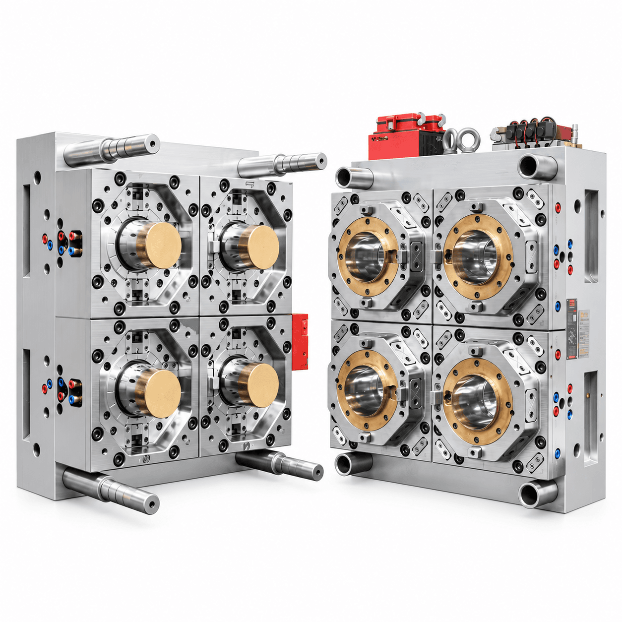
A bucket can leave the mould looking round and still distort after cooling, stacking or filling. Thin regions may show incomplete filling or weak handling performance, while heavy local sections can cool differently from the main wall. The correct acceptance question is not simply whether one sample looks good. Buyers need an approved drawing, a measurement plan and stable-process evidence across cavities. This guide focuses on wall thickness and shape, complementing separate lid-fit and handle-strength qualification.
Define the Part and the Measurement Datum
Provide controlled drawings for the bucket, base, rim, stacking features and any handle attachment. Identify resin grade, colorant, nominal capacity, target mass, production machine, cavity count, filling conditions and cooling arrangement. Mark drawing revisions and the surfaces used as measurement datums. A bucket sitting on an uneven table can appear warped even when the base is within specification; the inspection fixture and support points must therefore be agreed before sampling.
Specify where wall thickness matters: near the rim, upper and lower sidewall, gate, base corners, ribs and handle-lug transitions. Define height and angular positions so different inspectors measure the same points. Do not set a universal wall-thickness number from a generic article. The target depends on product size, resin, filling, stacking and approved design. Include clear tolerances, test method and acceptance authority on the buyer's drawing.
| Buyer-controlled input | Inspection decision | Evidence retained |
|---|---|---|
| Approved bucket and feature drawings | Datums, dimensions and tolerances | Revision-controlled inspection plan |
| Resin and colorant specification | Shrinkage and processing comparison | Material identification and trial record |
| Machine, cavity and output target | Representative FAT run | Cavity-labelled samples and settings |
| Fill and stacking conditions | Functional qualification boundary | Test plan and package samples |
| Cooling and handling layout | Timing of ejection and measurement | Water, take-out and conditioning log |
Review Wall Distribution Before Cutting Steel
Connect geometry to flow and packing
Review transitions between the broad sidewall and thicker rim, base, ribs and lugs. Abrupt thickness differences can change filling and cooling; a very thin region may require higher pressure or show incomplete fill. Ask the tooling team to explain gate location, flow length, packing path and expected variation around the circumference. A flow analysis can inform discussion, but it does not replace measurements from the actual tool and resin.
Check cooling and ejection together
Uneven cooling and shrinkage are known causes of warpage, as described in Autodesk's moulding guidance. For a bucket, review water circuits near the base, sidewall and rim, along with any inserts that create local hot spots. Ejecting too early can permit deformation outside the mould; holding the part longer may affect output. Discuss cooling, part support, take-out gripping and cycle time as one production decision, not independent promises.
Define Shape Checks That Match the Use
Agree how to assess base flatness, sidewall roundness or ovality, verticality, rim geometry and nesting or stacking features. State whether a check occurs immediately after ejection, after a defined conditioning period, or both. Plastics continue to change temperature after mould opening, so the time and support condition must travel with each measurement. Photographing a single bucket on a bench is not a substitute for a measured profile.
Where the application needs a mating lid, use the approved lid and closure procedure for a functional check; treat the detailed sealing and stack-load study as a separate package qualification. If a handle is fitted, retain its approved revision for later loaded tests. This keeps the wall-and-shape FAT focused without pretending it certifies the entire filled package.
Build a Traceable Factory Acceptance Trial
Stabilize before collecting samples
Record resin and colorant lot, machine, mould revision, active cavities, cycle conditions, cooling-water supply and take-out method. Define the stabilization period and reject start-up samples from the acceptance set. Identify every retained bucket by cavity and collection time. Sample more than one consecutive cycle so the buyer can see whether a dimension drifts, not merely whether one part passes.
Measure thickness and shape consistently
Use the agreed thickness gauge, cut-section method or other approved equipment at the mapped locations. Record the instrument and calibration status, orientation, operator and sample condition. Check mass, wall thickness, base and rim geometry, visible sink, short fill and deformation using the same part IDs. Report individual cavity results rather than only an average: an outlying cavity can be hidden by a satisfactory overall mean.
If a result fails, preserve its cavity ID and settings. Separate a tool-geometry issue from material, packing, cooling, ejection or handling changes before altering steel. Agree the corrective action and repeat the relevant measurement under the original method. A process adjustment that makes one specimen pass does not demonstrate a stable production window.
Separate FAT From Site Package Qualification
At FAT, the supplier can demonstrate the stated bucket dimensions and repeatable appearance under recorded equipment and material conditions. Filled-bucket handling, long storage, transport vibration, real stacking and lid sealing may require the buyer's production environment. List these as open site tests with owner and acceptance criteria; do not silently mark them passed because the empty bucket looks acceptable.
Before shipment, request approved drawings, thickness map, raw cavity records, measurement setup, retained samples, water-connection map, trial video, open-issue register and spare insert list. Protect critical rim and base surfaces during packing. At site restart, compare machine, water, material and take-out with FAT, then repeat agreed measurements after stable production. A change in conditioning time or support fixture can change the apparent warpage even when the mould is unchanged.
Conclusion
Wall thickness and warpage should be accepted through defined locations, datums, conditioning and cavity-level evidence. Review flow, cooling and ejection before machining; then test the real mould under stable conditions. Keep the limits of mould FAT separate from filled-package performance so both supplier and buyer know what remains to be proven.
Frequently asked questions
Is one wall-thickness reading enough?
No. Use the approved map across rim, sidewall, base and critical features, with identified cavity and orientation. One point cannot show circumferential or cavity variation.
When should bucket warpage be measured?
At the time specified by the buyer's method. Measurements immediately after ejection and after conditioning answer different questions; record both when needed.
Can longer cooling always fix a warped bucket?
No. Part geometry, resin, packing, cooling balance, ejection and handling can all contribute. Diagnose the cause before accepting a cycle-time penalty as the solution.
Does an empty-bucket FAT approve stacking or sealing?
No. It confirms only the stated moulding and dimensional conditions. Filled-package stacking and lid sealing need their own application-specific tests.
Talk to a mould engineer
Discuss a bucket wall-and-shape FAT: Send your bucket drawing, resin, fill and stacking requirements, machine details and expected output for a practical thickness map and acceptance plan.
Get a Quote →