
Mould Engineering · 11 min read
Published: October 5, 2026
Packaging Mould Cooling Water: Utility Specification and FAT Guide
Turn cooling-water assumptions into a documented interface between the mould supplier and the receiving factory.
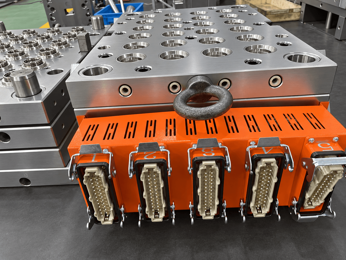
A mould can pass a short factory trial and still run differently at the customer's plant because the available cooling water is not the same. In PET preform, cap and bucket projects, temperature stability and circuit performance affect part dimensions, release and repeatable cycle time. A quotation that says only “connect cooling water” leaves the most important interface undefined.
This guide shows packaging buyers how to document that interface before tooling approval, what to observe during factory acceptance testing (FAT), and what to repeat after installation. It is not a universal water-temperature recipe. The mould supplier, machine supplier and receiving plant must agree project-specific limits using their actual equipment manuals and water-treatment advice.
Define the Site Utilities Before Approving the Tool
Ask the receiving factory for its cooling-system description: chilled or tower loop, supply and return conditions, available pressure and flow at the machine connection, filtration, water-treatment programme, hose sizes, connection standards and any temperature-control unit. Separate what the plant can supply continuously from a short peak reading. Identify which team owns the machine side, mould side and treatment programme.
Share the injection-machine model, platen layout, mould footprint and production target with the toolmaker. If a robot, hot runner or auxiliary device has its own cooling demand, keep those loads in the utility schedule rather than silently assigning them to the mould. The final agreed schedule should identify measurement locations and operating conditions; figures copied from another machine are not project specifications.
| Buyer input | Supplier decision | Acceptance evidence |
|---|---|---|
| Site supply and return conditions | Circuit and manifold design | Agreed interface schedule |
| Available flow and pressure at connection | Pump and hose compatibility | Measured FAT and site readings |
| Water quality and treatment ownership | Corrosion and deposit controls | Treatment plan and monitoring record |
| Machine, mould and auxiliary loads | Separate utility connections | Marked connection diagram |
| Production target and part criteria | Stable trial condition | Cycle, dimensions and sample log |
Map the Cooling Circuits as a Maintainable System
Identify every supply and return path
Request a circuit diagram showing inlet, outlet, manifold, branch and the parts of the mould served by each path. Label physical connectors to match that diagram. Agree how the plant will isolate, flush and reconnect a circuit without confusing supply and return. A useful handover allows a maintenance technician to trace a low-flow branch without dismantling the mould.
The map should distinguish the mould from machine, hot-runner and downstream-equipment cooling. For a multi-cavity preform tool, ask how representative regions are observed; for caps and buckets, identify zones relevant to thread, rim, wall or base stability. Do not assume that one manifold reading proves equal flow everywhere.
Review connections and leak protection
Check hose routing, connector clearance, strain relief, lifting and service access. Document the permitted connection type and any sensor or interlock that protects against running without adequate water. Agree a leak-check procedure before the first heated trial and after transport. A small leak near electrical controls or a hot runner is more than a housekeeping issue.
Specify Water Quality Without Inventing Universal Limits
Assign treatment responsibility
The receiving plant should arrange water analysis and treatment appropriate to its local supply and system. Husky's published machine guidance warns that corrosion and deposits in cooling channels can reduce heat transfer and damage components, and recommends a site-specific treatment programme. That is a reason to request a plan, not to copy chemistry values from a different machine or water source.
Ask who samples water, which loop is sampled, how often readings are reviewed, and who responds to out-of-range results. Define responsibilities for filtration, flushing, lay-up or storage protection and restarting after an extended shutdown. The mould supplier should identify materials and internal passages that impose specific requirements; the plant should confirm its treatment can meet them.
Monitor the condition that matters
Agree where supply and return temperature, flow and pressure will be recorded during a stable trial. Note water quality measurements only when the chosen treatment specialist and equipment manuals define the method and limit. A single inlet temperature does not show whether a branch is blocked, reversed or insufficiently supplied. Log alarms or flow-switch events with the trial condition.
If moulded parts vary, compare the water record with cavity or zone samples before changing tooling. A dimension shift may result from material, process, machine or cooling; one reading alone does not establish root cause. Preserve the original data and the result of each corrective action.
Make Cooling Evidence Part of FAT
Before trial, agree the machine, resin, mould revision, set-up, stabilization criteria and sample plan. Record the water-source configuration, actual connection points and measurement instruments. The FAT conditions need not be identical to the buyer's plant, but the differences must be visible so nobody treats the factory cycle as a guaranteed site result.
Observe flow and temperature under load
After stabilization, record supply and return conditions at agreed locations, flow or branch observations where instrumentation permits, leak checks and alarms. Record conditions throughout the sample window, not only a photograph of a display at start-up. If a branch cannot be measured directly, say so and define a practical indirect check or a site follow-up item rather than inventing evidence.
Link utility data to part quality
Identify samples by cavity or mould zone and time. Measure the dimensions and functions relevant to the product: for preforms, neck and gate condition; for caps, thread and sealing features; for buckets, rim and wall shape. Document cycle observations and any cooling-related defect with the matching water and machine settings. Retest a correction under a comparable condition; a faster isolated cycle is not proof of stable production.
Prepare Shipment and Site Commissioning
Before shipping, provide the final circuit and connector map, approved utility schedule, FAT log, sample identification, maintenance and flushing instructions, spare seals or fittings agreed in the contract, and packing photographs. Protect open water ports against contamination and label the inlets and returns so the receiving team does not have to infer them.
At installation, confirm the real hose connection, filtration, available flow and pressure, water treatment, leak status and sensor function before running production. Repeat the critical sample and utility checks after stabilization. Compare site results with the documented FAT configuration and record differences. If quality or cycle diverges, investigate the full system before blaming the mould or increasing cooling demand beyond plant capacity.
Conclusion
Cooling water is a buyer–supplier interface, not a footnote in a mould quotation. A site utility schedule, traceable circuit map, treatment ownership and matched FAT/commissioning records give both sides a practical basis for acceptance and troubleshooting. Values must come from the actual equipment and plant, not a generic article.
Frequently asked questions
Can the FAT cycle time be guaranteed at our plant?
Only if the complete operating assumptions are agreed and reproduced. Different water, machine, material or handling conditions can change a site result; record those differences before judging the tool.
Is one manifold temperature reading enough?
No. It does not establish branch flow, return condition or uniform cooling. Use the circuit map and the measurements available at agreed points.
Who specifies water chemistry?
The receiving plant and qualified treatment specialist should define a programme using local water analysis and equipment requirements. The toolmaker must disclose any mould-material or passage constraints.
What if a branch cannot be measured during FAT?
Record the limitation and use an agreed indirect observation or site follow-up. Never list an unperformed flow check as a pass.
Talk to a mould engineer
Request a cooling-water interface review: Send your mould and machine details, available water conditions, production target and part drawing for a practical utility schedule and FAT plan.
Get a Quote →