
Plastic Cap Moulds · 10 min read
Published: September 30, 2026
Plastic Cap Mould Cycle Time and Cooling: A Buyer Evaluation Guide
Evaluate cap-mould cycle-time claims against cooling, ejection, machine fit and stable trial evidence.
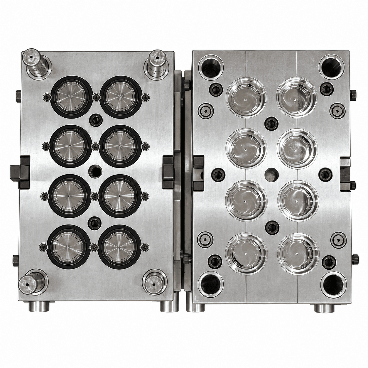
When buyers compare cap-mould proposals, the shortest quoted cycle time is often treated as the decisive number. It should not be. A useful cap-mould evaluation asks whether the proposed cycle can be repeated with the actual cap, resin, cavity count, injection machine, cooling-water system and quality requirements.
This guide explains how cooling, ejection, hot-runner behavior and machine interfaces influence cycle time for water caps, CSD closures, oil caps, flip tops and other plastic closures. Its aim is to help buyers evaluate output claims without asking a mould maker to make an unsupported promise.
Cycle Time Is a System Result
Cycle time is the complete recurring sequence required to make a set of caps, not simply the cooling period. Injection, holding, plastication, cooling, mould opening, unscrewing or stripping where applicable, ejection, part removal and mould closing all occupy time or affect how much cooling is needed.
The proposed figure must be linked to a specific application. A thin-wall water cap, a tethered closure and a flip-top cap have different geometry, material flow, ejection and functional requirements. A generic “fast cycle” statement is not a usable production basis.
| Review item | Buyer question |
|---|---|
| Cap design and weight | Which revision, wall sections, thread and tamper features are assumed? |
| Resin | Which PP or HDPE grade and color condition were considered? |
| Cavitation | How are filling, cooling and ejection managed across all cavities? |
| Injection machine | Is shot capacity, clamp, platen spacing and interface fit confirmed? |
| Cooling utilities | What water temperature, flow and treatment assumptions are needed? |
| Trial evidence | What was actually observed and recorded at the factory? |
How Cooling Influences Quality and Output
Cooling removes heat from the moulded cap so it can be ejected without unacceptable distortion, thread damage, shrink-related function issues or surface marks. In high-cavity tools, consistency is often more valuable than reducing a few tenths of a second in a trial that cannot be sustained.
Water circuits are part of the specification
Ask for labeled water circuits, connection sizes, a circuit diagram where supplied, and the utility expectations used for the trial. Water quality, scale, flow restriction and uneven temperature can alter cooling performance after installation. A clean, documented cooling layout is also easier for the maintenance team to inspect and service.
Ejection must match the cap design
Some caps strip, some use unscrewing mechanisms, and some require application-specific handling. Review thread geometry, tamper band, sealing area, mould release and the proposed ejection method together. A cap that survives ejection but suffers thread damage or functional variation does not support a reliable cycle claim.
Hot runner stability matters too
Temperature control, melt balance and gate condition affect the window in which the tool can run. During a trial, inspect representative cavities for gate appearance, short shots, flash, cap weight and visual consistency. Do not assume that a cooling issue can be fixed solely by reducing or increasing mould-water temperature.
Compare Output Proposals Honestly
Production capacity is usually calculated from cavities, cycle time, operating hours and an efficiency assumption. The calculation is helpful only when each assumption is visible. Ask a supplier to show the formula and identify what has not been included: start-up scrap, color changes, planned maintenance, downstream handling or operator interruptions.
For example, two quotations may show the same annual output while relying on different operating days, cycle assumptions or downtime allowances. The buyer should compare stable, saleable output rather than cavities multiplied by an optimistic cycle.
What to Ask During Factory Testing
Agree a test plan before the mould trial. A useful record can include:
- The cap drawing and resin used for the trial
- Machine identity and relevant process settings
- A stable observed cycle, identified as a trial result rather than a guaranteed site value
- Samples from agreed cavities and visual or dimensional checks
- Cooling, ejection and mould-motion observations
- Known open points and actions before shipment
If a matching bottle is available, add a fit or function check appropriate to the closure. This does not replace filling-line validation, but it makes the FAT more connected to the packaging system.
Prepare the Receiving Plant
Before shipment, confirm electrical voltage and connector requirements, hot-runner controller responsibility, water fittings, hydraulic or pneumatic interfaces, lifting method and spare parts. The receiving plant should verify its chiller capacity, water treatment, machine clearance and part-handling path before the tool arrives.
At installation, start with documented utility checks and controlled samples. If the installed cycle differs from the factory observation, compare the entire system—material, machine, water, process and automation—before assigning cause to the mould.
Frequently asked questions
Can a supplier guarantee a cap-mould cycle time?
A supplier can state a proposal and document a factory observation, but site performance depends on the actual resin, machine, utilities, process and operating discipline. Specify the conditions behind any target.
Does colder water always create a faster cycle?
Not necessarily. Cooling must remain uniform and appropriate for the resin and cap geometry. Very different water conditions can create quality or stability problems.
Is higher cavitation always the best way to increase output?
No. Higher cavitation also increases the requirements for machine fit, melt balance, cooling, maintenance and handling. Compare the whole production cell and total investment.
Talk to a mould engineer
Request a cap-mould cycle review: Send your cap drawing, resin, cavity target, injection-machine data and available cooling-utility details for a practical output evaluation.
Get a Quote →